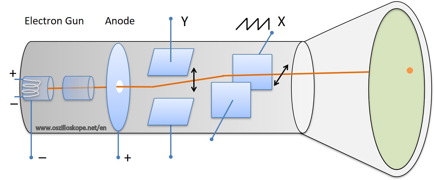
Cathode ray tube for an analog oscilloscope.
Analog oscilloscope: layout of the cathode ray tube.
An analog oscilloscope is based on an electron beam tube. That principle is similar to old televisions, where these devices are called tubes. A heating element first heats a tungsten wire. This causes electrons to be "ejected" from the wire. A positive voltage at the anode accelerates the electrodes. They pass through the hole in the anode. A vertical Y deflection is archived by a plate capacitor. The signal to be measured is sent to the vertical plate capacitor. Depending on the voltage, the electrons are deflected up or down, they follow the measured voltage signal. In the X-direction, the deflection takes place by a 90° angle turned plate capacitor, to which a sawtooth voltage is applied. This ensures that the beam is always deflected from left to right. A detailed description of the electron beam tube is described in the section layout and operating principle .
An analog oscilloscope needs internally a multitude of setting parameters (voltage amplification at the plate capacitors) as well as a heavy and complex picture tube (vacuum technology). Because of the high production costs and the more complicated handling they were largely displaced by digital oscilloscopes. Today they aren't be produced anymore. In the hobby area, however, they are still useful and can be found on the second hand market.