An oscilloscope consists of a display, setting knobs for the time base, the controllers for the signal voltage and input channels for connecting a probe. The subpage oscilloscope usage explains these elements in more detail. There are two types of oscilloscopes: analogue and digital ones.
Layout and operating principle of an analog oscilloscope
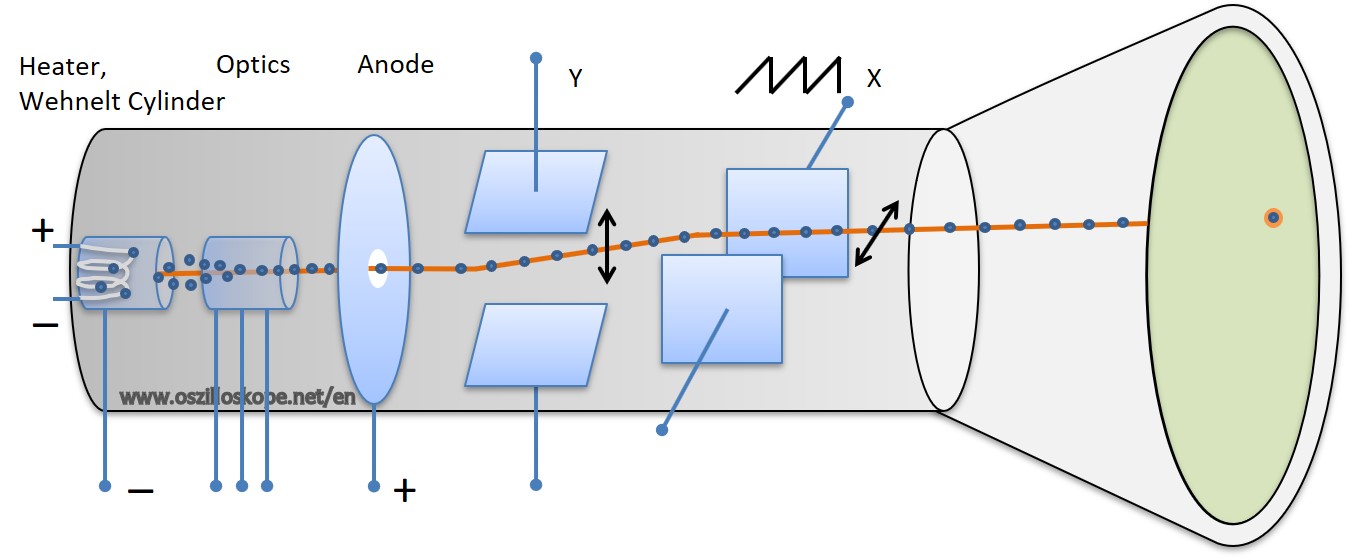
Layout and operating principle of an analog oscillosope: the cathode ray tube with an electron gun.
The analog oscilloscope is essentially based on the so-called electron beam or cathode ray tube. The cathode ray tube is comparable to tubes in old televisions. The upper picture shows the cathode ray tube. On the far left there is a heating wire that is made to glow by an electrical current. The heating wire or an electrode behind it is charged negatively: the so-called cathode. By heating up the wire the electrons from the cathode (-) and are drawn towards the anode (+). This is based on the physical principle of electrostatic attraction or repulsion. Two negative charges repel each other, one positive and negative charge attract each other. The electrons move from the cathode to the right towards the anode. There is a vacuum inside the tube, thus electrons cannot react with air particles. Around the heating wire one can find the so-called Wehnelt cylinder. This cylinder is slightly negatively charged right at the opening. The negative voltage causes the electrons to flow towards the opening. It is important here that the voltage of the Wehnelt cylinder is not too high. A strongly negative current would prevent the flow of electrons. The cylinder is followed by further focusing optics in front of the anode. It is used to focus the beam by different electrical potentials, called as electron optics.
The anode itself also has an opening. The individual electrons are accelerated so strongly that they miss their target (the anode). They are accelerated to fly past the opening. Without further influence, the electrons now hit the middle of the screen and create a luminous spot. A plate capacitor with one plate on top and one plate at the bottom of the screen ensures that the electron beam can be directed upwards or downwards. The signal to be measured is transmitted to these plates (after analog gain). If the upper plate is represents the positive signal amplitude, the electrons are pulled upwards. Is it negative, the electrons are pressed down. This results in an electron beam in Y direction porportional to the measuring signal. Two further plates in X-direction move the beam from left to right. The oscilloscope drives the X-plates with a saw tooth signal. The beam follows the saw tooth and moves from left to right. In Y-direction it follows the waveform to be measured. The frequency of the sawtooth determines the sampling of the analog signal. The frequency is set by the time base setting. At the end of the tube there is a fluorescent screen. The electron beam hits the screen and makes the phosphorescent layer glow. The phosphor in the screen glows for a while, sampling the signal for several milliseconds.
The control of the electron beam tube requires a multitude of gain factors and other parameters. In addition, the waveform of an analog oscilloscope cannot be stored digitally, they can only be "photographed". Similar to the tube televisions analog oscilloscopes are superseeded by modern digital oscilloscopes with LCD display. Nevertheless, an analog oscilloscope is usefull vor simple measuring tasks. Used analog oscilloscope can be found on the on the second-hand market and are very inexpensive.
Layout and operating principle of digital oscilloscopes
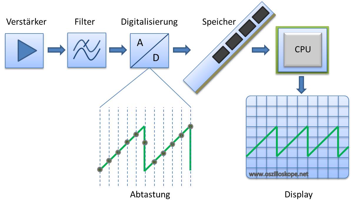
Layout and operating principle of digital oscilloscopes - A/D conversion and data processing.
The picture shows the layout and working principle of a digital oscilloscope. The measuring signal is analogiously amplified and filtered. Filtering is necessary due to the digital scanning process, which limits the upper frequency (by the bandwidth of the oscilloscope). If frequencies higher than the sampling rate occur in the measurement signal, the too low sampling rate leads to misinterpretation of the signal (see Aliasing). The actual scanning is done by an analog-to-digital converter, which samples the signal in fixed time intervals. The frequency of the discrete sampling must be a multiple of the signal frequency in order to detect steep edges properly. The bandwidth of an oscilloscope is therefore an important purchase criterion. The signal amplitude is converted into discrete values. A 10-bit A/D converter can handle 2^10 signal stages, i.e. 1024 different discrete values. An 8-bit A/D converter, on the other hand, can only handle 256 different levels. A higher number of bits for the A/D converter is advantageous. The digitized data is written into a memory. A processor reads out the data and is displayed at the screen of the oscilloscope. Since the data is in the memory anyway, it is possible to apply various algorithms such as FFTs or other mathematical operators. In addition, the data can be stored on a USB stick, compact Flash or an SD card. For older oscilloscopes there are adapters from Compact Flash to SD slots.
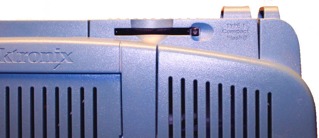
Memory slot within a digital oscilloscope.
Digital oscilloscopes have largely replaced their analog counterparts. The simpler hardware and cheaper technology has resulted in a large distribution of digital oscilloscopes in the hobby sector. They are available for a few hundred dollars. Digital oscilloscopes are available in many bandwidths and memory sizes. Large memory devices are also called storage oscilloscopes or transient recorders.