The interactive graphic shows the adjustment of a probe. By clicking the probe trimmer the capacity changes. Most oscilloscopes output a test frequency of 1kHz. This frequency is applied to the probe and the measured signal is displayed on the scope.
Schematic
Why does a probe need compensation? The following schematic explains why the calibration is necessary and reasonable and how the compensation works.
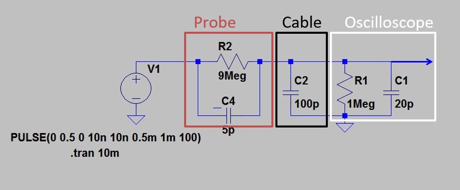
Probe compensation: Circuit diagram.
The figure above shows a simplified equivalent circuit diagram of oscilloscope (white), cable (black) and probe (red). The circuit diagram and the simulation were created with the free software LTSpice (here for Windows and MacOS available). The schematic can be used for your own experiments on this downloaded subpage.
The oscilloscope has an input impedance of one Megaohm and an input capacitance of approx. 20pF. The values are not exact and vary slightly from device to device. The cable (black) has a capacity of approx. 100pF, also with tolerances from cable to cable. The probe has an input resistance of 9 Megaohm. This results in a divider ratio of 10:1. The capacity of C4 is variable in the form of a trim capacitor. Usually there is a small screw on the tip of the probe or on the BNC connector. With a screwdriver, you can turn the screw and thus vary the capacity between 5-20pF.
All above mentioned capacities are only roughly given. If the probe is not calibrated, a frequency-dependent distortion of the signal shape is measured. The above simulator and the following illustrations show the distortions caused by a wrong trim capacitor value.
Insufficient compensation

Probe compensation: trim capacity too low.
The illustration shows a simulation of the measured input signal at the oscilloscope, if a square wave voltage with a frequency of of 1000Hz is present. The simulation shows the case of an insufficient compensation. The trimming capacitance of the capacitor is too low. It can be seen that both the rising and falling of the signal is too slow.
Over compensation
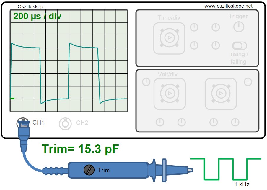
Probe compensation: The capacity of the trim capacitor is too high.
Overcompensation occurs when the trim capacity is too high. In this case, the rising edge shoots above the target value. The falling edge goes below the zero level, before the the curve slowly approaches the zero line.
Correct compensation
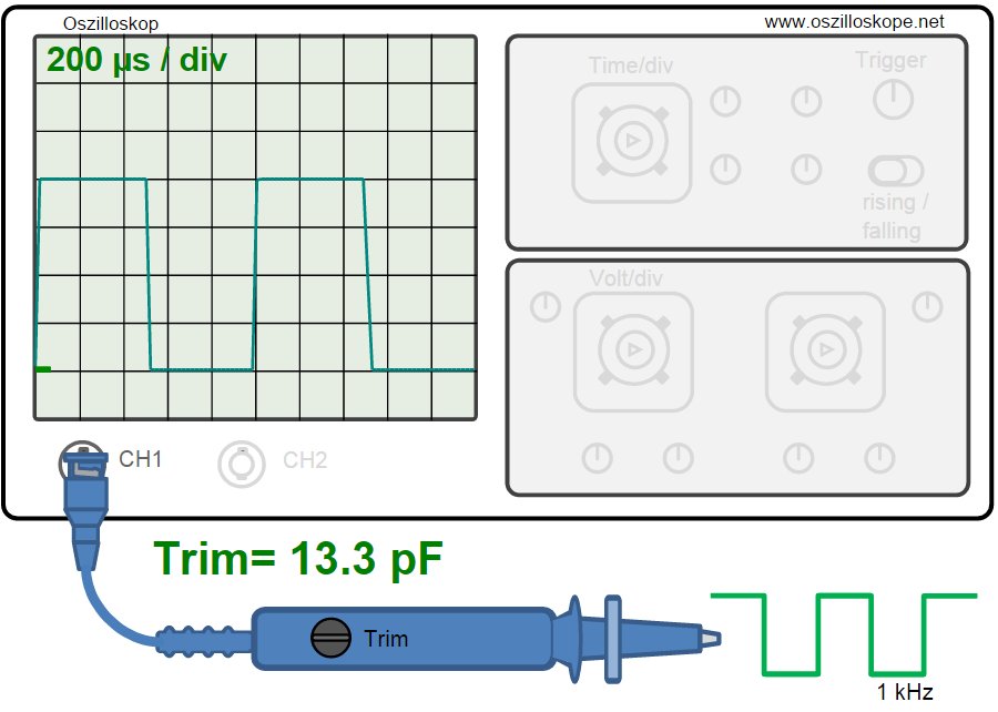
Correct probe compensation.
The probe head is correctly compensated if the square wave oscillation at the oscilloscope input has clean edges and the input oscillation follows correctly.
Probe compensation
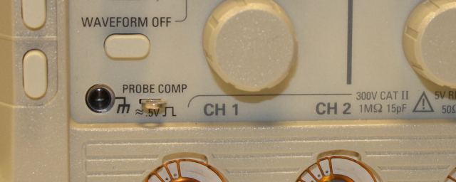
Contact for probe compensation on the oscilloscope.
So how do you calibrate the probe of an oscilloscope? Most oscilloscopes have a special contacts on the front panel. This metal contact supplies a rectangular oscillation, which can be touched the tip of the probe. You connect the probe to an oscilloscope channel and touches the pin "probe compensation". The Oscilloscope screen displays a (possibly deformed) rectangular vibration. As shown in the diagrams above, you must now rotate the trimming capacitor of the probe until a rectangular oscillation with sharp edges appears on the screen. The probe has been correctly compensated. The trimming capacitor is located in the upper part of the probe or on the BNC connector.
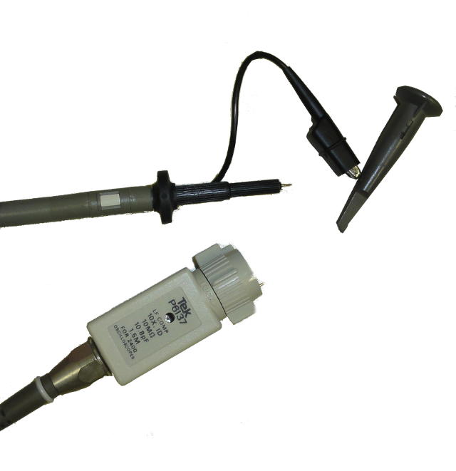
Probe with trim capacitor at the bnc socket.
Instruction video for probe compensation: