Principle and definition of an oscilloscope
What is an oscilloscope? An oscilloscope is a measuring device for imaging electrical signals. The special function of oscilloscopes is the time-dependent display of the signal form. In contrast to other measuring devices such as multimeters, oscilloscopes show the temporal course of the signal on a graphic display. One axis of the representation is time, the other axis represents signal intensity. A (memory) oscilloscope is also named as oscillograph .
Layout and working principle
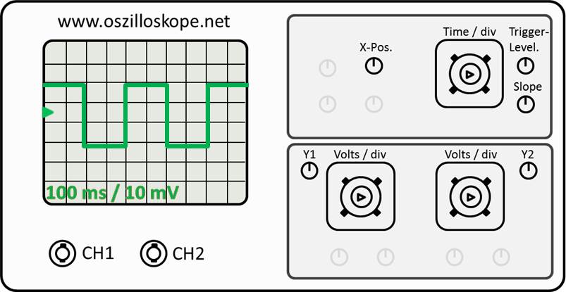
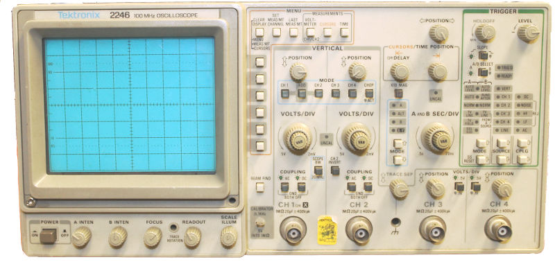
Oscilloscopes always have a very similar layout. The following short Introduction summarizes the layout. First, there is a (BNC) connection for each measuring channel, here marked CH1 and CH2. A probe is connected to these channels. There is a large display to display the waveform to be measured. On the X axis, the the time, on the Y-axis the signal intensity are displayed. Frequently you can find the current settings of the oscilloscope at the bottom of the display. One important parameter is the so-called time base. This value specifies how much measurement time corresponds to a division (here 100 ms). The value is displayed in s/div, i.e. in seconds per division (=box). The parameter is set via Time/div. Finally, it is used to set the sampling rate.
The other important parameter is the signal representation in mV/div. Setting 10 mV means that a div represents a signal amplitude of 10mV. This value is calculated using a rotary knob Volt/div set for each channel. Besides there are also numerous setting options for the trigger, the trigger level as well as the representation of the signal form. You can take single-shot measurements or work continuously (running). The signal can be mathematically transformed e.g. by an FFT analysis or displayed in XY mode. The article about oscilloscope usage explains these topics mentioned above in more detail.
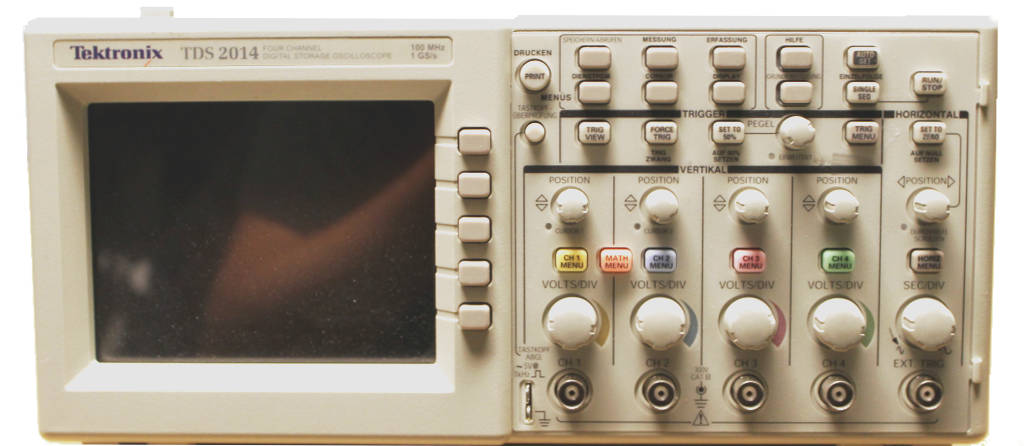
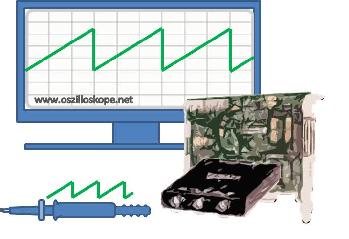
Oscilloscopes differ in detail depending on the type of instrument in analog or digital oscilloscopes. Analog oscilloscopes are based on the deflection of a cathode beam. Digital oscilloscopes scan the waveforms and store them in a digital memory. The article Layout and operating principle is dedicated to the differences between analog and digital systems. Digital oscilloscopes are the more modern devices and you can find them even for a personal computer or as USB oscilloscope. PC and USB devices are usually designed as additional boards for the computer, while analog and digital oscilloscopes are usually freestanding devices.
Measuring with an oscilloscope
First you should ask yourself about what you actually want to measure. Is there is only a DC voltage signal or a sinusoidal AC voltage to be measured. For simple tasks use a multimeter (also have a look at further information about measuring voltage here). For non sinusoidal alternating voltage you will need an oscilloscope.
How Do I measure with an oscilloscope
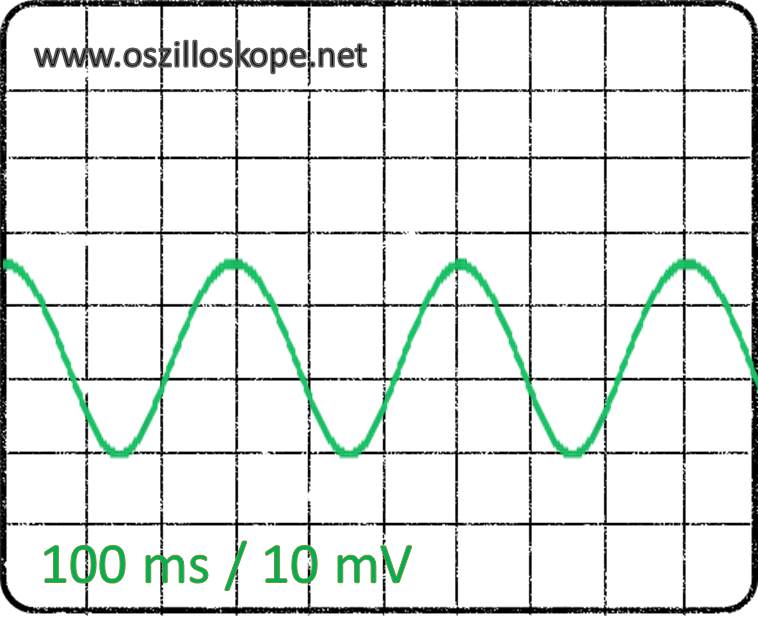
First you have to connect the test setup accordingly and adjust the oscilloscope (see section oscilloscope usage , you can find a description of the various controls). Next, you have to enter the time base and signal amplitude. In the case of sinusoidal oscillation shown above use e.g. 100 ms / div and 10 mV signal amplitude per div. The above sine wave has an amplitude of two and a half divs. This results in a signal amplitude of 2.5 * 10mV = 25 mV. The oscillation period is 3 divs, i.e. from maximum to maximum in this case is 3*100ms=300ms. This corresponds to a frequency of f=1/300ms=3.33 Hz.
Trigger
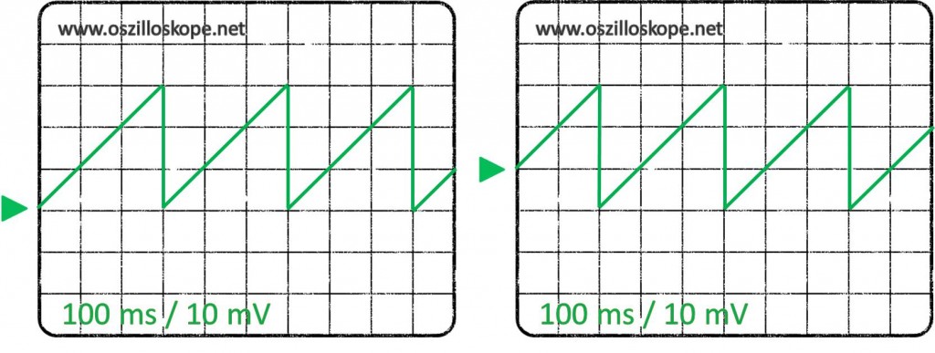
Each oscilloscope has a so-called trigger, which controls the display of the signal on the screen. A trigger is is actually a component that triggers a switching operation. The trigger synchronizes the oscilloscopes display with the signal. The example above shows two trigger settings with slightly different settings. In the left image, the trigger level (green arrow) is at the third last box. The sawtooth signal increases from this position by three divs and falls back to zero after 300ms. If you now increase the trigger level by one div, the resulting signal is shown n the right picture. The trigger level defines the point in time at which the signal is picked up and is displayed on the screen. Compared to the left picture the increased trigger levels shifts the display to the left. The waste of the sawtooth signal to zero is now displayed after 200 ms. The oscilloscope trigger only affects the display of the signal. In example above, the sawtooth signal still has an amplitude of 30 mV and a period of 300 ms, the measured signal therefore remains independent from the trigger setting. Oscilloscopes typically have many setting options for the trigger. Besides level you can also select the slope. Furthermore you can select external signals, single-shot measurements or measure continously.
Probe
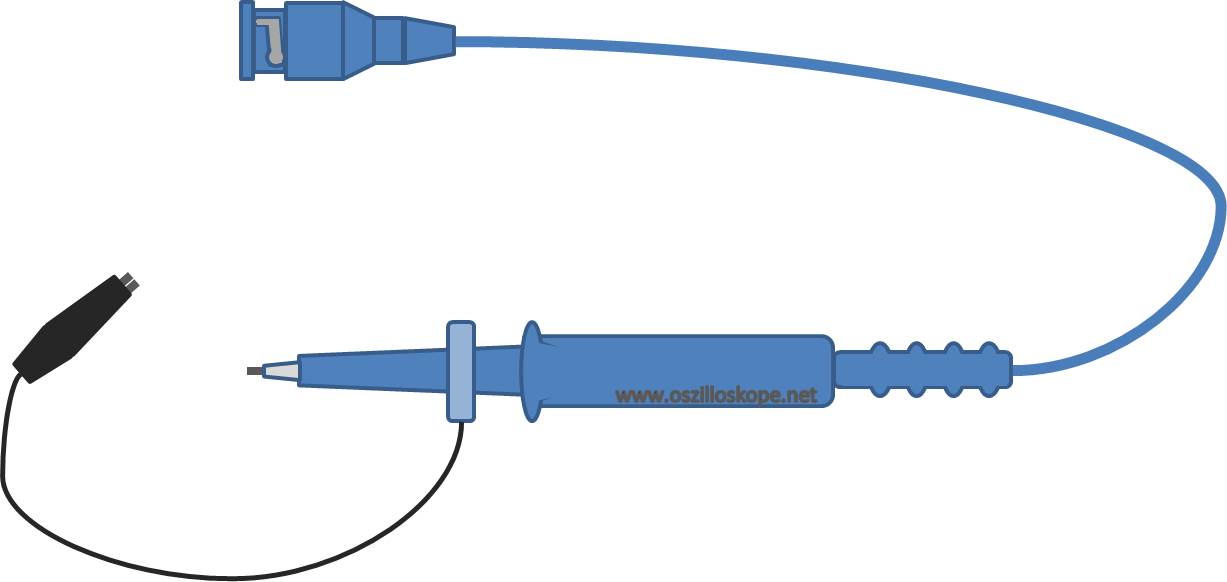
The probe head of an oscilloscope is used to pick up the sample to be tested under defined conditions. The probe has a defined impedance (resistance and capacitance) and thus allows the measurement of a signal with as little influence as possible. On the one end the probe is connected to the oscilloscope with a BNC connector. On the other end there is a metal contact for acquisition of the measuring signal. Often there is also a pickup to hold and measure cable ends. The second connection of the probe is in the form of a crocodile clip and is equipped with the ground line of the oscilloscope. The correct wiring of the probe mass is an issue for itself.
Probes often have an adjustable attenuation ratio, e.g. 1 and 10. An attenuation factor of 1 means that the signal amplitude is unaffected by the probe and is transmitted to the oscilloscope. An attenuation factor of 10 means that the signal is transmitted to the oscilloscope divided by 10. To avoid a wrong interpretation, the oscilloscope must be given the division ratio set on the probe. This is what you do either via the oscilloscope menu or via a "intelligent" probe. The manufacturers of intelligent probes add additional lines to the probe and oscilloscope. You can recognize this by additional pins next to the BNC connector. The impedance of the probe can be manually adjusted. Further information about probes can be found on the probe subpage.
Analog oscilloscope
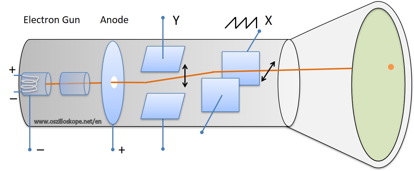
The first generation of oscilloscopes were analog systems similar to tube televisions. The basis of a analog oscilloscopes is the electron beam tube with integrated deflection, as shown above. The principle is simple: there is an electron beam inside a vacuum tube generated by electrical voltage and is deflected by a high voltage capacitor. At the end of the tube, the electron beam hits a screen and creates a luminous point. The individual elements of the cathode ray tube are the electron gun, focusing optics, the anode, the deflection in Y- and X-direction as well as the fluorescent screen. In the tube, the filament and an accelerating voltage generates an electron beam towards the display. Capacitor plates at the top / bottom and left / right deflect the beam depending on the applied voltage. The article Layout and operating principle describes the electron beam tube of the analog oscillograph more precisely.
Digital Oscilloscope
The signal path of a digital oscilloscope consists of an amplifier, a filter, a digitization and a subsequent transfer to memory. Amplifiers and filters are used for analog preprocessing. Then the actual sampling of the signal is done by an A/D (analog-digital converter). The amplitude values are written to a memory and are processed by a processor. The final result is shown on the display. The page Layout and operating principle describes the design an working principle im more detail. The digital data can be used for a later post-processing and can also be stored on a USB stick. This is not possible with analog oscilloscopes. Variants of digital oscilloscopes are PC oscilloscopes and USB oscilloscopes.
PC oscilloscope
PC oscilloscopes are special forms of the digital oscilloscope. They exist in two common designs: as plug-in card for the PC or as card for the USB port. The plug-in cards are stored as PCI cards in the computer and are permanently installed. A special connection is used to connect the cables from the analog input and output and numerous digital IO pins. PCI plug-in cards are used in automation technology because they have many triggering options and have a very good software integration. Depending on supported programming language and drivers, the cards can be used under Windows, Mac or Linux. In case of doubt, please refer to the manufacturer's data sheet about the supported computer architectures and software environments. The manufacturer National Instruments offers a special graphical programming language called LabView, which is frequently found in measurement and automation technology.
A simple PC oscilloscope can also be build with a sound card and a corresponding software.
USB oscilloscope
Besides plug-in cards there are USB (universal serial bus)-based oscilloscopes. These are often boxes with BNC connectors for the channels on one side and a USB port on the other side. The USB card is connected to the computer and controlled or read out by software. Depending on manufacturers support the USB devices supports different programming languages, so that you can use them well in your own measurement tasks. The USB cards usually do not have as many channels as the plug-in cards, however, have the advantage of more flexible use. One can quickly plug the USB card into another computer or use it with a laptop. If you are using a USB oscilloscope with a laptop, you can work completely battery-buffered and thus avoid mass problems.
Software
There are numerous software projects for the PC that deal with oscilloscopes. For example, there is freeware that uses the sound card as a simple oscilloscope. Here is a software oscilloscope for the PC sound card (GUI in Labview). A list of other popular soundcard tools (also for Linux) can be found here.
On our site you can find an online simulator for an oscilloscope and frequency generator. It runs in the browser and also works with mobile phones and tablets. Click simulator for this online tool.
In the app stores for Android and IPhone are numerous tools that can record signals via the microphone and display the waveform. The Android app Oscilloscope Pro supports microphones and a special USB hardware to measure real voltage signals. Oscilloscope apps are also available for the Iphone and Ipad.
You can find also software for using an oscilloscope as an output. At the hacker party "Assembly" the group "tvt" has developed a demo in which the PC sound card is connected to the XY inputs of the oscilloscope. The corresponding sound output can be used to display figures on the oscilloscope.
This concept was further extended by Pekka Väänänen . He ported the popular game "Quake" to an oscilloscope.
Buying an oscilloscope
So what do you have to pay attention to when you want to buy a device? First, you should consider what bandwidth you need. The bandwidth should be at least twice as high as the maximum bandwidth of the signal to be measured. Here you have to note that square-wave signals contain multiples of the fundamental frequency, where the bandwidth should be at least a factor 10 above the square wave basic frequency. Another important criterion is the number of channels. The minimum amount of channels should be two channels. Four-channel oscilloscopes are a good choice for more experienced users. If the budget is very tight, perhaps a used analog oscilloscope might be an option.
